Tuesday, 21 May 2013
Thursday, 2 May 2013
Rear brake lines
There is a well known issue with using the VW / hydra mechanical rear callipers. Mainly the brake line banjo ends up being to close for comfort to the drive shaft gator.....Apart from this issue I wanted to use the VW callipers as they are nice and light being made of alloy. So, although I've not fitted the drive shafts yet, I have the luxury of reading the other J15 (Vectis) blogs and seeing the problem before I started.
So, how to overcome this.......while removing a set of callipers from a VW Passat at the local scrap yard, I wrenched off the ends of the brake lines. As you can see the Banjo is relatively thin, this of course means the banjo bolt is also smaller too.
This means the bolt used is considerably smaller, and if used with a thinner banjo can save a fair amount of height. Note the hole in the banjo bolt both lined up in the picture. This shows the potential as to how much height can be reduced.
So, how to overcome this.......while removing a set of callipers from a VW Passat at the local scrap yard, I wrenched off the ends of the brake lines. As you can see the Banjo is relatively thin, this of course means the banjo bolt is also smaller too.
This means the bolt used is considerably smaller, and if used with a thinner banjo can save a fair amount of height. Note the hole in the banjo bolt both lined up in the picture. This shows the potential as to how much height can be reduced.
My guess is around 4-5mm reduction in height would be plenty, so 2mm off each side of the banjo and 2mm off the top of the bolt will give a total of 6mm which should mean there is no chance of it catching the drive shaft
Here it fitted...........Job done.Monday, 15 April 2013
Steering, Handbrake, Speedo
It's amazing how the pace of the build has slowed of recent. Most jobs now being done are the things that are not immediately obvious......So, the car sort of looks the same as it did a two months ago. However, I've not stopped, and have a few updates to report.
Lets start with the steering..........The IVA has some requirements surrounding the safety of the steering column. There are a number of ways to tackle this. If you can have more than 10degrees of angle between the column and the shaft that connects to the steering rack then this really helps. The J15 set up is boarder line, so I opted to use the Puma UJ that also has a collapsible component. This required a small shaft to be machined up that went through the front bulk head and onto the steering rack. OK, straightforward.......well, not really. Although it sounds obvious, by adding another UJ in the system, you also introduce some sag in the column. This sag manifests itself to the shaft flying around all over the place with you turn the wheel....Most certainly not ideal!. The 'simple' fix was to introduce a bearing to hold the shaft in position. I won't bore you with the details, but this turned out to be a bigger job than first expected due to the proximity of the bolts associated with the steering shaft.
Anyway.....with bearing installed with a stand off, all now works nicely with no play and a smooth action.
The handbrake (which has been mentioned before) has also been updated. I made the main cable up from the rear calliper cable from a Golf. The local yacht rigger (Jerry the rigger) has swagged the eyelet and M6 Thread onto the cable. The rear connection was removed from an Audi A4, and is simple in design. I need to trim the rear cables (from a Renault Megan), and that job should then be finished.
Finally for this update, the speedo sensor.....
Lets start with the steering..........The IVA has some requirements surrounding the safety of the steering column. There are a number of ways to tackle this. If you can have more than 10degrees of angle between the column and the shaft that connects to the steering rack then this really helps. The J15 set up is boarder line, so I opted to use the Puma UJ that also has a collapsible component. This required a small shaft to be machined up that went through the front bulk head and onto the steering rack. OK, straightforward.......well, not really. Although it sounds obvious, by adding another UJ in the system, you also introduce some sag in the column. This sag manifests itself to the shaft flying around all over the place with you turn the wheel....Most certainly not ideal!. The 'simple' fix was to introduce a bearing to hold the shaft in position. I won't bore you with the details, but this turned out to be a bigger job than first expected due to the proximity of the bolts associated with the steering shaft.
Anyway.....with bearing installed with a stand off, all now works nicely with no play and a smooth action.
The handbrake (which has been mentioned before) has also been updated. I made the main cable up from the rear calliper cable from a Golf. The local yacht rigger (Jerry the rigger) has swagged the eyelet and M6 Thread onto the cable. The rear connection was removed from an Audi A4, and is simple in design. I need to trim the rear cables (from a Renault Megan), and that job should then be finished.
Finally for this update, the speedo sensor.....
As you may be aware, I’m going to use a small digital dash…this
comes with a sensor that is magnetic. The basic theory is you find somewhere on
the car that is connected and revolves directly to the wheels (but has a magnetic
high point), point the sensor at it and program in the amount of pulses per 1
revolution of the wheel (you also program in the tyre circumference). I found a
convenient place on the drive shaft with three high points…..Hopefully, that
should be the last time I need to think about the sensor placement….we will
see!.
Tuesday, 19 March 2013
Forgot to post this in previous blog........As mentioned, I hoovered up a load of coolant pipes from the scrap yard.....End result lookis like this, All the hoses have build in bends so I was able to select some that fitted the application. The T piece at the top acts as a bleed as a few of the other builders have done.
Monday, 18 March 2013
Rad, fan, and some plumbing
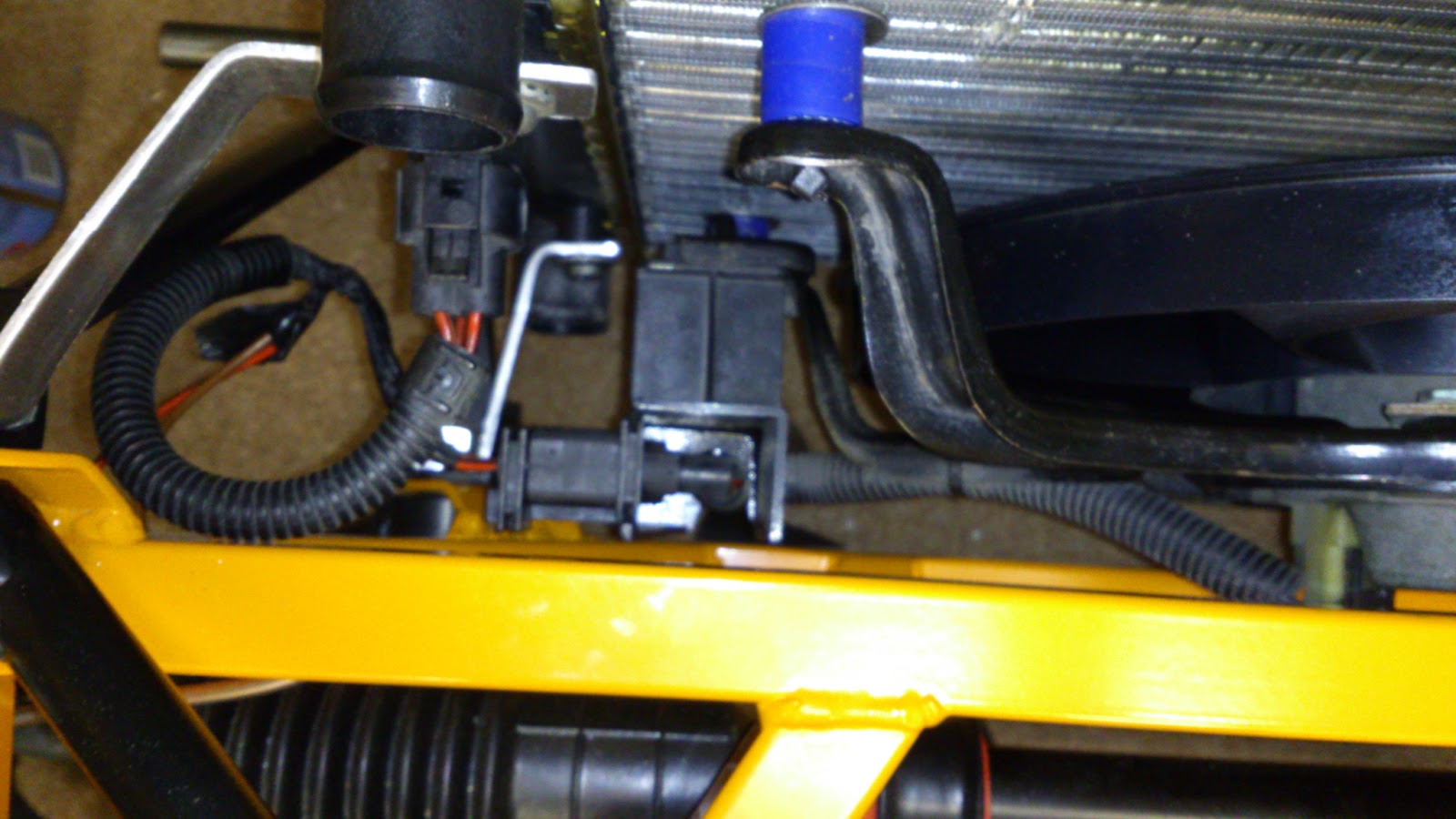
Not a massive amount of progress of recent, but I'm hoovering up some of the smaller jobs that need doing. I fitted the radiator some time ago, but was unhappy with the position. The arrival of the fan meant I could do some more measurements and it was too close to the chassis, so this gave a good excuse to redo the brackets.
Once again, in the interests of keeping things simple, I opted to make 4 alloy brackets that bolted direct to the wishbone mounts via the wishbone bolts. The frontal area of the chassis can be exposed, so the less drilling the better. This meant that the entire assembly did not require any additional chassis drilling.
As mentioned previously, the rad was new (for a golf mk4), and the fan was liberated from a Polo. I removed the fan from the scrap polo with the associated connectors and fan switch which meant that the install was neat enough thanks to mr VW. For the fan to fit, a stand off was required. The usual way of fitting a fan is to either use the fitting kits (which are basically ties that pass through the rad, or via some brackets that attach to the holes in the side of the rad. In the spirit of 'kit car' I devised my own which consisted of some large M6 stainless washers, cable ties, and and some old silicone tube I had lying around to act as the stand off.
One gripe I had was the material used for the cooling fins on the rad has the strength of tin foil. even if you look at it in a funny way, it bends!.
Thursday, 7 March 2013
Dash and Header tank
The digital dash arrived...I ended up going for a Koso DB1R Plus...The main reason was the size. Basically, there is bugger all room above the steering column, and this was one of the few that fitted. I'm sure other J15 builders will be questioning my taste when comes to this item, and quite rightly so. The J15 has fantastic lines, and is a classic shape, and an angular digital dash is not really in keeping with the design. But, as mentioned previously, I've always wanted to keep the car light weight, simple and uncluttered, and as the Koso has rpm, speed, warning lights and fuel level, it fits the bill. As you can see, once in position, it does offer a good view of the screen. It will be a while before it's fired up, and there are a few issues with the speedo signal to overcome.
Onto the header tank....I purchased this a while ago, and it was a bit grotty, but an hour with the autosol, and it looked liked something worthy or a new car. I made a couple of alloy brackets with rivnuts for the tank attachment they were then riveted to the chassis, the tank then simply screws in via some M6 bolts.
Ive also been raiding the scrap yard for waterhoses and a cooling fan...this has worked out well, as a bag of hoses of all different types costs a fiver, and fit very well. The fan came from a polo, and needed some mods to the frame, but again, it's a top quality bit of kit, and came with the fan temperature sensor/switch, and a nice bracket for the wiring....More pics of this lot fitted next time.
Thursday, 28 February 2013
Throttle pedal
I must admit, I didn't think much of the standard Sylva offering for a throttle pedal fixing. It consisted of a bolt with two nuts....theory being, bolt through a hole on the pedal box, slide on throttle pedal, tighten up one nut but not tight to the pedal, use the other nut as a locking nut......OK, I'm sure this would have been OK, but it did mean there was a fair amount of slop in the pedal (sideways), and also, the potential for the nuts to tighten up and jam the pedal was (I thought) too high. My basic thought was to simply put a bar across the entire box and slide the pedal over it with the appropriate spacers.
So, I gave my design brief to my engineering consultants (i.e. retired dad)......
In true engineering style, the brief turned into a mission to see just how good he could make a throttle pedal pivot....so a shaft was machined up with push through spacers, the pedal received a couple of high quality bearings that fitted....result...a pedal with no sideways movement whatsoever, and a very smooth action. Very pleased
So, I gave my design brief to my engineering consultants (i.e. retired dad)......
In true engineering style, the brief turned into a mission to see just how good he could make a throttle pedal pivot....so a shaft was machined up with push through spacers, the pedal received a couple of high quality bearings that fitted....result...a pedal with no sideways movement whatsoever, and a very smooth action. Very pleased
Subscribe to:
Posts (Atom)