Monday, 5 August 2013

Bonnet catches

Bonnet Catches - another subject I probably spent far too long thinking about!.

The demo car from Sylva uses some springs on the inside of body work. I liked this idea as they are well concealed........however, when I got the body work lined up, I felt there was a little bit too much 'spring' in the fibreglass to be held by a spring alone. I figured a more secure and direct method may keep the shut lines a little neater. There are plenty of catches around, but of course, IVA is something you must consider, so this meant only a few were actually suitable for the job. I ended going with the 'aerocatch' TYPE arrangement. I say the aerocatch TYPE as my first effort was purchased from China (they looked the same!). these turned out to be aerocatch copies and surprise, surprise...broke after 5 mins (that's £18 down the drain). Lesson learnt, correct and proper Aerocatches promptly ordered....

Drilling the hole was simple enough. The catches come with a template. so it's a matter of  marking the position, drilingl two holes with a holesaw (one 44mm, the other 25mm), then cut the bit out in the middle, a bit of fileing and sanding and you're there.....Note: as with all things fiberglass, it helps to mask the area first  and use a higher drill speed. 


.........and fitted. you can see the square cut out in the front clam, this forms two functions a). allows the red anodised pin free entry to the catch, and b). I wasn't happy with the pin going direct into the fibreglass, so strengthened it with some ally on the top and bottom.

The nice thing about the aerocatches is you can set them up so you need to push down on the bonnet with a fair amount of pressure to locate the pin, this in turn keeps the shut lines looking good. They are also very tactile and have a pleasing action (ok, this is getting a bit weird now!).


The alignment work is by no means finished, and the body work needs to come back off to finish the wiring. Other things to do include reinforcing the area where the clam is attached to the pivots.

Another success story was the holes for the front lights. Common practise is to chain drill (the hole is approx 125mm dia), but I hate chain drilling (not sure why). I purchased (for £2.99) a hole cutter from ebay. this was the type with the two outriggers with a cutting blade at each end. The items are recommended for use in a pillar drill, but I figured I could get this to work with a steady hand and my mains powered drill. It was admittedly very scarey, if something goes wrong you could trash the clam. However, it didn't go wrong and I was left with two well finished holes of the correct size....Will try and post some pics of this later.

Saturday, 13 July 2013

Brake cylinders, front clam fixing and a very nice wheel

The fixing of the front clam was another part of the build that I wasn't entirely looking forward to. The first step is to get the clam in position then mark out and install two fiberglass panels into the front to a), stiffen up the clam and b): to give a fixing point for the brackets.

I decided to tackle this by hanging the clam first on some fixing points that I attached to the main tub, these points will act as a lip and support and help spread the load. With the panels marked I fiberglassed in the supports.

There have been some discussions on the locost forum recently regarding the fitment of integral master cylinders. From my experience, I don't seem to have an issue with them, but there are a few variables that could mean they don't fit certain cars....the biggest of which being a different pedal box for the earlier cars. Here are some pics of the three cylinders. Note the two brake cylinders are angled slightly down to get a better alignment with the bias adjustment bar, but to be honest this is probably not necessary. Also, I used some fiesta level indicators that fit the wilwood cylinders and are actually slightly lower than the wilwood cap. Again, this may help with clearance.

NOTE AND UPDATE: Having now completed the front body work alignment, there appears to be plenty of room for integral master cylinders with out having to angle them......I'm not sure why other can't fit them. but I don't see an issue using this set up.


Finally, a friend of mine was kind enough to let me borrow one of his 13 inch wheels from his caterham R300 (sorry, R419 since the engine was changed :-) ), this has made me more determined than ever to squeeze some 13" wheels on. These particular ones were a whopping 8 inch rim width, and wouldn't fit home, but I'm sure that a 6 inch rim would go on....To do this, I may need to put some subtle wheel arch extensions on and go with a offset of around 24, but I really feel it can be done.

You have to admit, it really does look good though!..


Thursday, 2 May 2013

Rear brake lines

 There is a well known issue with using the VW / hydra mechanical rear callipers. Mainly the brake line banjo ends up being to close for comfort to the drive shaft gator.....Apart from this issue I wanted to use the VW callipers as they are nice and light being made of alloy. So, although I've not fitted the drive shafts yet, I have the luxury of reading the other J15 (Vectis) blogs and seeing the problem before I started.

So, how to overcome this.......while removing a set of callipers from a VW Passat at the local scrap yard, I wrenched off the ends of the brake lines. As you can see the Banjo is relatively thin, this of course means the banjo bolt is also smaller too.

This means the bolt used is considerably smaller, and if used with a thinner banjo can save a fair amount of height. Note the hole in the banjo bolt both lined up in the picture. This shows the potential as to how much height can be reduced.

My guess is around 4-5mm reduction in height would be plenty, so 2mm off each side of the banjo and 2mm off the top of the bolt will give a total of 6mm which should mean there is no chance of it catching the drive shaft
 Here it fitted...........Job done.


Monday, 15 April 2013

Steering, Handbrake, Speedo

It's amazing how the pace of the build has slowed of recent. Most jobs now being done are the things that are not immediately obvious......So, the car sort of looks the same as it did a two months ago. However, I've not stopped, and have a few updates to report.

Lets start with the steering..........The IVA has some requirements surrounding the safety of the steering column. There are a number of ways to tackle this. If you can have more than 10degrees of angle between the column and the shaft that connects to the steering rack then this really helps. The J15 set up is boarder line, so I opted to use the Puma UJ that also has a collapsible component. This required a small shaft to be machined up that went through the front bulk head and onto the steering rack. OK, straightforward.......well, not really. Although it sounds obvious, by adding another UJ in the system, you also introduce some sag in the column. This sag manifests itself to the shaft flying around all over the place with you turn the wheel....Most certainly not ideal!. The 'simple' fix was to introduce a bearing to hold the shaft in position. I won't bore you with the details, but this turned out to be a bigger job than first expected due to the proximity of the bolts associated with the steering shaft.

Anyway.....with bearing installed with a stand off, all now works nicely with no play and a smooth action.

The handbrake (which has been mentioned before) has also been updated. I made the main cable up from the rear calliper cable from a Golf. The local yacht rigger (Jerry the rigger) has swagged the eyelet and M6 Thread onto the cable. The rear connection was removed from an Audi A4, and is simple in design. I need to trim the rear cables (from a Renault Megan), and that job should then be finished.


Finally for this update, the speedo sensor.....
As you may be aware, I’m going to use a small digital dash…this comes with a sensor that is magnetic. The basic theory is you find somewhere on the car that is connected and revolves directly to the wheels (but has a magnetic high point), point the sensor at it and program in the amount of pulses per 1 revolution of the wheel (you also program in the tyre circumference). I found a convenient place on the drive shaft with three high points…..Hopefully, that should be the last time I need to think about the sensor placement….we will see!.


Tuesday, 19 March 2013


Forgot to post this in previous blog........As mentioned, I hoovered up a load of coolant pipes from the scrap yard.....End result lookis like this, All the hoses have build in bends so I was able to select some that fitted the application. The T piece at the top acts as a bleed as a few of the other builders have done.

Monday, 18 March 2013

Rad, fan, and some plumbing


Not a massive amount of progress of recent, but I'm hoovering up some of the smaller jobs that need doing. I fitted the radiator some time ago, but was unhappy with the position. The arrival of the fan meant I could do some more measurements and it was too close to the chassis, so this gave a good excuse to redo the brackets.

Once again, in the interests of keeping things simple, I opted to make 4 alloy brackets that bolted direct to the wishbone mounts via the wishbone bolts. The frontal area of the chassis can be exposed, so the less drilling the better. This meant that the entire assembly did not require any additional chassis drilling.

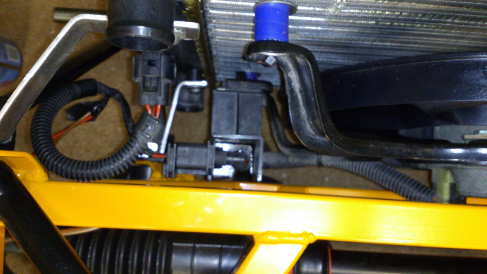
As mentioned previously, the rad was new (for a golf mk4), and the fan was liberated from a Polo. I removed the fan from the scrap polo with the associated connectors and fan switch which meant that the install was neat enough thanks to mr VW. For the fan to fit, a stand off was required. The usual way of fitting a fan is to either use the fitting kits (which are basically ties that pass through the rad, or via some brackets that attach to the holes in the side of the rad. In the spirit of 'kit car' I devised my own which consisted of some large M6 stainless washers, cable ties, and and some old silicone tube I had lying around to act as the stand off.


One gripe I had was the material used for the cooling fins on the rad has the strength of tin foil. even if you look at it in a funny way, it bends!.